Key points
- Automotive embedded systems combine hardware, firmware and vehicle interfaces.
- CAN and LIN require suitable transceivers and physical-layer design.
- Power supply protection is a core engineering requirement.
- Diagnostics and observability reduce integration and support effort.
- Bench testing must be followed by real-vehicle validation.
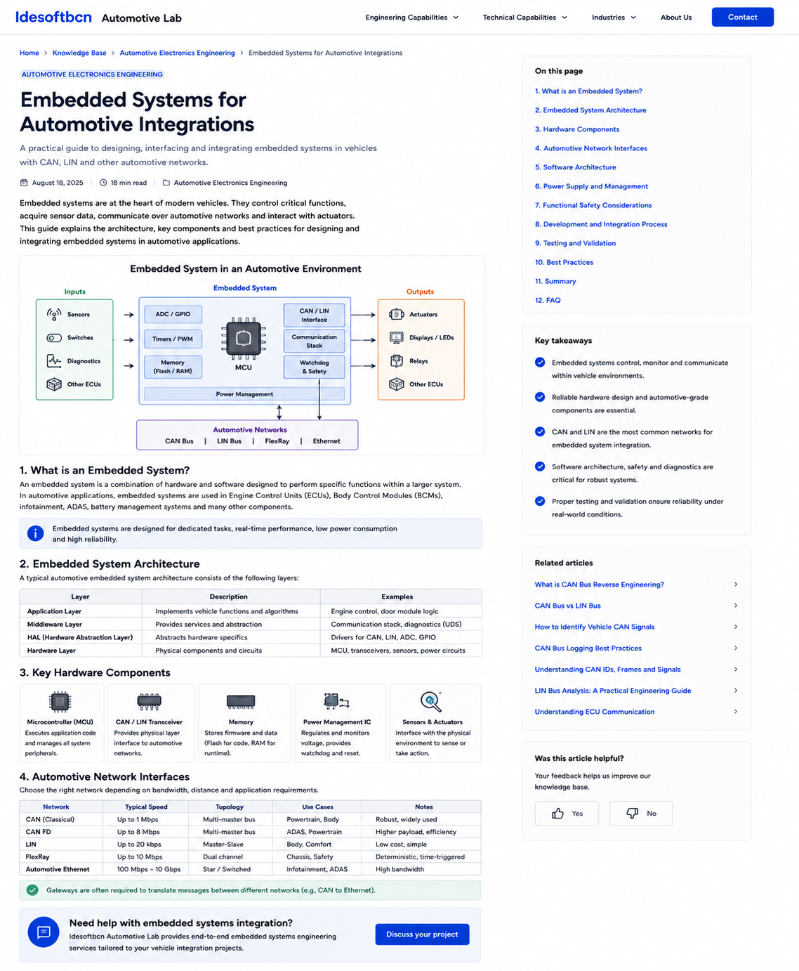
1. What is an automotive embedded system?
An automotive embedded system is a purpose-built combination of electronics and software designed to perform a defined function inside a vehicle. It can monitor sensors, execute control logic, communicate with other electronic control units and operate actuators or displays.
Typical examples include gateways, telematics units, retrofit controllers, sensor nodes, diagnostic interfaces and dedicated actuator modules.
2. Embedded system architecture
A maintainable design separates the application, middleware, drivers and physical hardware. This reduces coupling and makes the platform easier to test, modify and reuse.
| Layer | Responsibility | Examples |
|---|---|---|
| Application | Implements vehicle functions and decision logic. | Gateway rules, monitoring, actuator control. |
| Middleware | Provides shared services. | Diagnostics, communication stacks, data storage. |
| Hardware abstraction and drivers | Controls MCU peripherals and hides hardware details. | CAN, LIN, ADC, GPIO, timers and PWM. |
| Hardware | Provides the physical electronic platform. | MCU, transceivers, memory, power and protection. |
3. Key hardware components
Microcontroller
The microcontroller executes firmware, handles timing, manages communication and interfaces with external peripherals. Selection depends on processing needs, memory, peripherals, temperature range, qualification and lifecycle availability.
Network transceivers
CAN, CAN FD and LIN transceivers convert MCU logic-level signals into the electrical signaling used on vehicle networks. They may also provide wake-up support, fault protection and low-power behavior.
Power management
Power-management circuits regulate the vehicle supply, supervise voltage, control resets and manage sleep and wake-up states.
Protection and interfaces
External connectors require protection against electrostatic discharge, reverse polarity, transients and electrical noise. Sensors and outputs may also need filtering, amplification or dedicated driver stages.
4. Automotive network interfaces
| Network | Typical role | Main considerations |
|---|---|---|
| CAN / CAN FD | Distributed control and vehicle data. | Bit rate, termination, bus load, timing and error handling. |
| LIN | Low-cost local sensors and actuators. | Master schedule, frame identifiers, timing and wake-up. |
| Automotive Ethernet | High-bandwidth communication. | Switching, addressing, diagnostics, security and EMC. |
| Diagnostics | Configuration, service and testing. | UDS services, sessions, security access and transport. |
5. Software architecture
Firmware should remain deterministic, observable and recoverable. Common building blocks include a scheduler or RTOS, state machines, communication drivers, diagnostic services, persistent configuration, logging and watchdog supervision.
- Separate network communication from application logic.
- Define explicit startup, normal, sleep and fault states.
- Validate external inputs before using them.
- Record diagnostic information for field analysis.
- Use controlled, versioned firmware and configuration releases.
6. Power supply and vehicle electrical conditions
A vehicle supply is not equivalent to a clean laboratory power source. The embedded system may experience cold cranking, jump start, load dump, reverse polarity, ground offsets and conducted electrical noise.
Power design must also consider quiescent current, wake-up sources, delayed shutdown and correct recovery after interrupted power transitions.
7. Safety and fault handling
The required development rigor depends on the function and associated risk. Even when formal functional-safety compliance is not required, useful engineering practices include failure-mode analysis, plausibility checks, communication timeouts, watchdogs and safe fallback behavior.
8. Development and integration process
- Define requirements: interfaces, timing, environment, diagnostics and failure behavior.
- Design the hardware: MCU, power, protection, transceivers and connectors.
- Develop firmware: drivers, communication, application logic and diagnostics.
- Integrate on the bench: simulate vehicle signals and operating states.
- Test abnormal conditions: malformed frames, disconnections and voltage variation.
- Validate on the vehicle: confirm compatibility, timing, power modes and behavior.
- Document and release: preserve pinout, protocol, firmware and test evidence.
9. Testing and validation
Validation should cover functional behavior, timing, power cycles, sleep and wake-up, network faults, supply variation, environmental conditions and long-duration operation.
- Measure current consumption in all power states.
- Confirm behavior when messages are missing or invalid.
- Verify timing under realistic bus load.
- Test recovery after resets and interrupted updates.
- Repeat final tests on the target vehicle.
FAQ
Frequently asked questions
What is an automotive embedded system?
An automotive embedded system combines dedicated hardware and software to monitor, control or communicate with specific vehicle functions.
Why are CAN and LIN transceivers required?
The microcontroller handles protocol logic, while the transceiver provides the physical electrical interface and protection required by the vehicle network.
How should an embedded device be powered in a vehicle?
The design should account for cranking, load dump, reverse polarity, voltage transients, electrical noise, sleep current and wake-up behavior.
How are embedded automotive integrations validated?
Validation usually combines bench testing, network simulation, fault injection, power-cycle testing and final confirmation on the real vehicle.
Embedded engineering support
Need help integrating electronics into a vehicle?
Idesoftbcn Automotive Lab supports embedded hardware, firmware, CAN and LIN integration, diagnostics and real-vehicle validation.
Discuss your projectContinue reading