Key points
- Define the physical signal before starting the capture.
- Record clean, repeatable datasets under controlled conditions.
- Use message activity, timing and bit-level changes to reduce candidates.
- Determine byte order, length, scaling, offset and units methodically.
- Validate each candidate across multiple operating states before using it.
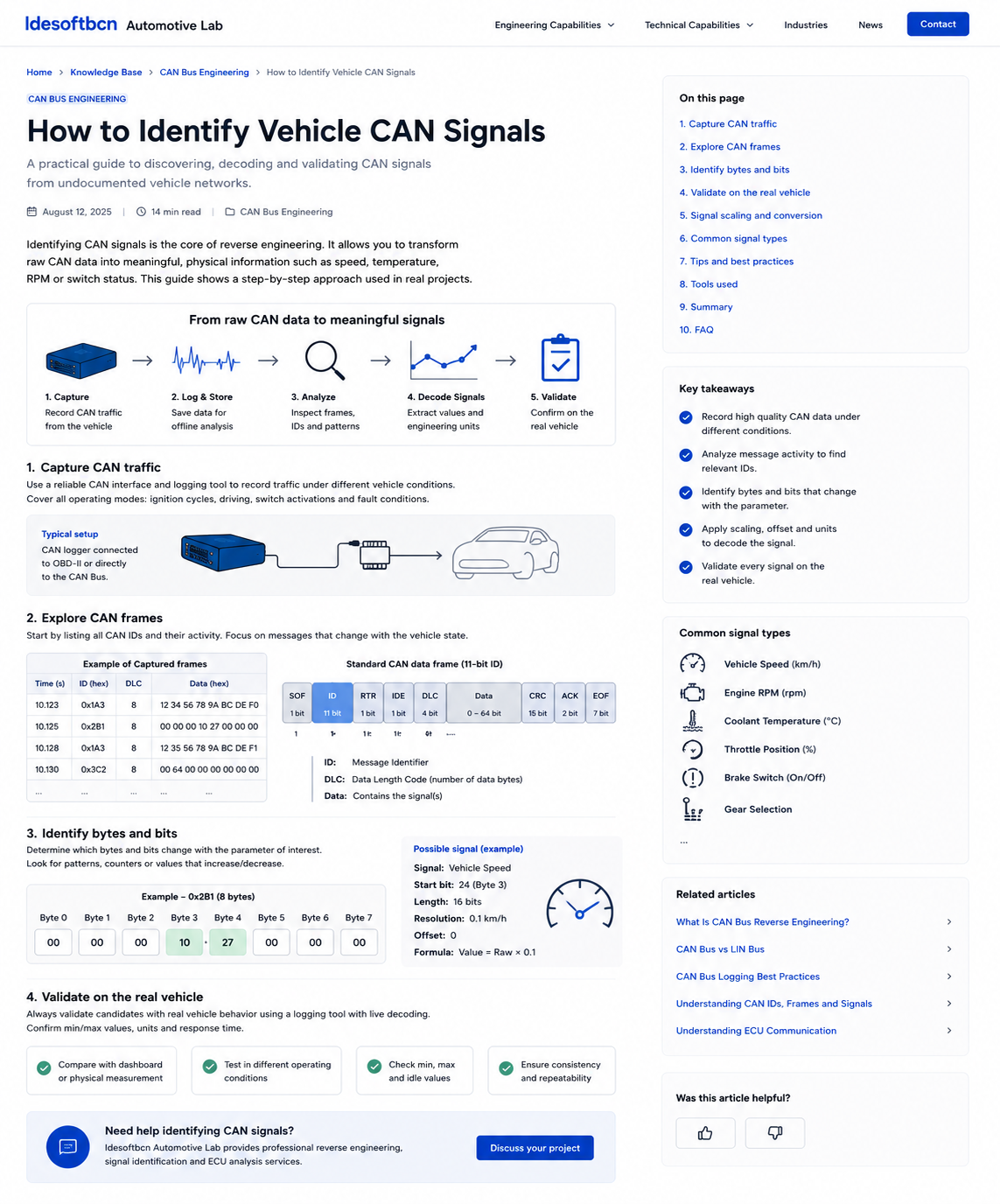
1. Capture clean CAN traffic
The quality of the final interpretation depends on the quality of the original recording. Connect a suitable CAN interface to the correct network, confirm the bitrate and verify that traffic is being recorded without dropped frames or timestamp instability.
Before changing any vehicle state, record a baseline. Note the ignition mode, engine state, battery voltage, active accessories and whether the vehicle has recently entered or exited sleep. These conditions can strongly influence which ECUs are awake and which messages are present.
Use controlled experiments
Change one variable at a time. To identify a door state, operate one door while keeping the others closed. To identify vehicle speed, perform a controlled speed profile. To identify a switch, press it repeatedly with clear pauses. Synchronized notes, event markers or video make later correlation much easier.
2. Explore CAN frames and message activity
Start by listing the identifiers present in the capture, their cycle times and how often their payload changes. Periodic messages often represent continuously transmitted states, while event-driven messages may appear only during a specific action.
Compare a quiet baseline against one or more action captures. Candidate identifiers are those whose payload changes at the expected time and returns to the previous state when the action is reversed. Repeating the experiment helps distinguish a real relationship from unrelated background traffic.
| Observation | Possible interpretation | What to check next |
|---|---|---|
| Single bit toggles | Boolean state or switch | Repeat action and test edge cases |
| Value rises smoothly | Sensor or calculated physical value | Compare with reference measurement |
| Byte increments continuously | Counter or rolling value | Check modulo behaviour |
| Several bytes change together | Multiplexed data, checksum or related state | Isolate action and inspect bit fields |
3. Identify the relevant bytes and bits
Once a candidate identifier has been found, inspect its payload at bit level. A signal may occupy one bit, a nibble, one byte or a multi-byte field. The location should be inferred from repeated observations rather than from one isolated sample.
Look for boundaries that remain consistent across the dataset. For a switch, the same bit should toggle in the same direction every time. For a sensor, the same group of bits should vary coherently with the physical value. Sudden discontinuities may indicate signed encoding, wrap-around, multiplexing or an incorrect byte order assumption.
Check byte order
Multi-byte signals may use little-endian or big-endian ordering. Plot both interpretations against the reference value and choose the one that produces a physically plausible and repeatable relationship. Avoid assuming byte order purely from platform or manufacturer conventions.
4. Determine scaling, offset and engineering units
A decoded raw value is not yet a complete engineering signal. The physical value is commonly obtained by applying a factor and an offset. Several reference points are needed to determine that relationship reliably.
For example, compare the candidate against a trusted speed, pressure, temperature or position reference at multiple values. Fit the simplest relationship that explains the data, then test values that were not used during the initial calculation. This prevents a coincidental match based on only two samples.
Also determine valid range, update rate, resolution and any special values used for unavailable, invalid or fault states. These details are important when the signal will be consumed by embedded firmware, a gateway, a data logger or a cloud API.
5. Validate the signal on the real vehicle
Validation should reproduce the expected behaviour under several conditions. Test minimum and maximum values, repeated ignition cycles, sleep and wake transitions, rapid changes and any relevant fault or degraded modes.
Where possible, compare the decoded result with an independent reference such as an instrumented sensor, diagnostic parameter, dashboard indication or external measurement device. The goal is not simply to produce a plausible graph, but to demonstrate that the signal remains correct across the operating range required by the project.
If the product must support multiple vehicles, repeat the validation on representative models, years and variants. CAN identifiers and encodings may change between platforms, production revisions or equipment levels.
6. Common vehicle signal types
- Boolean states: doors, brake switch, ignition, seat belt or warning states.
- Enumerated states: gear selection, drive mode, wiper mode or lighting state.
- Continuous values: speed, RPM, temperatures, pressures and positions.
- Counters and timing fields: rolling counters, alive values and message sequence numbers.
- Diagnostic states: warning flags, fault states and availability indicators.
Different signal types require different validation methods. A Boolean signal needs repeated state transitions, while a continuous signal requires several points across its range. Enumerated fields must be tested through every reachable state.
7. Document the result
A useful deliverable should let another engineer reproduce the interpretation. Record the network, CAN identifier, frame type, cycle time, start bit, bit length, byte order, signedness, scaling, offset, units and valid values. Include the vehicle configuration, test conditions, evidence and confidence level.
It is also good practice to preserve the original captures and analysis notes. Raw evidence makes future verification possible when a new vehicle variant, software revision or integration requirement appears.
FAQ
Frequently asked questions
Can software automatically identify every CAN signal?
No. Tools can accelerate filtering, plotting and correlation, but controlled experiments and engineering judgement remain essential.
Why do several CAN bytes change during one action?
One physical action may affect several ECUs, counters, checksums and state machines at once. Repetition and isolation help identify the meaningful field.
What should be documented for a decoded signal?
Document the bus, identifier, cycle time, byte order, start bit, length, scaling, offset, units, valid states, test conditions and confidence level.
Engineering support
Need to identify undocumented vehicle signals?
Idesoftbcn Automotive Lab provides CAN Bus reverse engineering, ECU signal discovery, embedded integration and real-vehicle validation.
Discuss your projectContinue reading