Key points
- The CAN identifier controls arbitration and helps receivers decide which messages to process.
- A CAN frame is the full transmitted message, including control and error-checking fields.
- The payload contains raw bytes; signals are logical values packed into selected bits.
- Signal decoding depends on start bit, length, byte order, signedness, scaling, offset and units.
- Every decoded signal should be validated against real vehicle behaviour.
1. CAN identifier
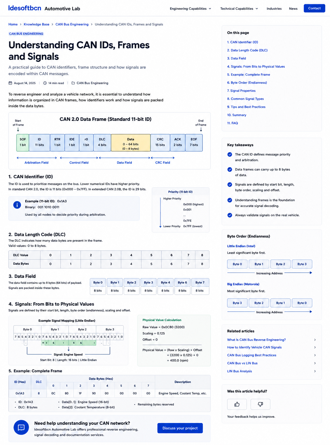
The CAN identifier is commonly called the CAN ID. In standard CAN it contains 11 bits, while extended CAN uses a 29-bit identifier. The identifier participates in arbitration: lower numerical identifiers have higher priority when multiple nodes attempt to transmit at the same time.
The identifier does not inherently contain a device address. Instead, it normally represents the meaning, priority or function of the message. Each receiving ECU decides whether the identifier is relevant and whether the payload should be processed.
| Identifier type | Length | Typical notation | Number of possible values |
|---|---|---|---|
| Standard CAN | 11 bits | 0x000–0x7FF | 2,048 |
| Extended CAN | 29 bits | 0x00000000–0x1FFFFFFF | 536,870,912 |
2. CAN frame structure
A classical CAN data frame contains more than the identifier and payload. It includes arbitration, control, error detection, acknowledgement and framing fields. These elements allow several ECUs to share one bus while detecting transmission faults.
| Field | Purpose |
|---|---|
| Start of frame | Marks the beginning of a new CAN frame. |
| Identifier | Defines arbitration priority and message meaning. |
| RTR / IDE / control bits | Describe the frame type and format. |
| DLC | Indicates the payload length. |
| Data | Contains the application payload. |
| CRC | Detects transmission errors. |
| ACK | Confirms that another node received the frame correctly. |
| End of frame | Marks the end of transmission. |
3. Data Length Code
The Data Length Code indicates how much payload data is carried by the frame. In Classical CAN, DLC values from 0 to 8 correspond directly to 0–8 data bytes. CAN FD supports longer payloads, with defined DLC mappings up to 64 bytes.
When analysing vehicle traffic, the DLC should be treated as part of the message definition. Two frames with the same identifier but unexpected payload length may indicate a different operating state, transport protocol or malformed capture.
4. Data field
The data field contains the raw payload. In Classical CAN it can contain up to eight bytes. These bytes do not carry units or labels by themselves. Their meaning comes from an external message definition or from reverse-engineering work.
A single payload may contain several values: for example, engine speed, coolant temperature, status flags, rolling counters and checksums can all share one frame. Some bits may be unused or reserved.
5. Signals: from bits to physical values
A CAN signal is a logical value extracted from a defined region of the payload. To decode a signal correctly, the following properties are normally required:
- Start bit.
- Signal length.
- Byte order.
- Signed or unsigned interpretation.
- Scale or factor.
- Offset.
- Physical unit.
- Valid minimum and maximum.
The usual conversion is:
Physical value = (raw value × scaling) + offset
For example, a 16-bit raw value of 3200 with a scaling factor of 0.125 and zero offset becomes 400 rpm.
6. Byte order
Multi-byte signals require a defined byte order. Little-endian signals place the least significant byte at the lower byte address. Big-endian signals place the most significant byte first. Automotive tools may describe these formats as Intel and Motorola byte order.
Endianness affects how bytes are assembled and how start bits are represented in some database formats. It should never be guessed from a single sample. Use repeated changes, known physical limits and tool-independent verification.
| Payload bytes | Little endian result | Big endian result |
|---|---|---|
| 0x12 0x34 | 0x3412 | 0x1234 |
7. Common signal properties
| Property | Example | Meaning |
|---|---|---|
| Start bit | 8 | First bit occupied by the signal. |
| Length | 16 bits | Number of payload bits used. |
| Signedness | Unsigned | How the binary value is interpreted. |
| Scaling | 0.125 | Multiplier applied to the raw value. |
| Offset | 0 | Value added after scaling. |
| Unit | rpm | Physical meaning of the decoded value. |
8. Complete frame example
Consider a frame with identifier 0x1A3, DLC 8 and payload:
0C 80 5A 90 00 00 00 00Suppose bytes 0 and 1 form a little-endian 16-bit engine-speed signal. The raw value is 0x800C, or 32780 decimal. If the scaling factor is 0.125 rpm per bit and the offset is zero, the decoded value is 4097.5 rpm.
Byte 2 may contain coolant temperature with an offset, while selected bits in byte 3 may indicate status flags. The exact interpretation depends on the real message definition and must be confirmed using measurements or controlled vehicle actions.
9. Practical decoding advice
- Inspect identifier, DLC and cycle time together.
- Do not assume that changing bytes represent one complete signal.
- Test both plausible byte orders for multi-byte candidates.
- Look for counters and checksums before treating them as physical values.
- Check whether the value saturates at plausible limits.
- Validate against dashboard, diagnostic or independent sensor data.
- Document confidence level and test conditions.
FAQ
Frequently asked questions
Does one CAN ID always represent one signal?
No. One CAN frame can contain several independent signals packed into different bits and bytes of the payload.
What is the difference between a CAN frame and a CAN signal?
A CAN frame is the complete transmitted message. A CAN signal is a logical value encoded inside the frame payload.
Why does byte order matter when decoding CAN signals?
Byte order determines how multi-byte values are assembled. Interpreting little-endian data as big-endian, or the reverse, produces incorrect raw values.
Engineering support
Need help decoding a vehicle CAN network?
Idesoftbcn Automotive Lab supports CAN capture, frame analysis, signal decoding, ECU reverse engineering and technical documentation.
Discuss your projectContinue reading